The Measure of Technology
Manual
Leakage Tester
Wöhler DP 600
.
Art. n°. 22915 – 2024-08-26

Contents
2
Contents
1 General Information .............................. 4
1.1 Operation Manual Information ...................... 4
1.2 Notes ............................................................. 4
1.3 Intended Use ................................................. 4
1.4 Components .................................................. 5
1.5 Transport ....................................................... 5
1.6 Information on disposal ................................. 5
1.7 Manufacturer ................................................. 5
2 Technical Data ....................................... 6
3 Component explanation ....................... 8
3.1 Device ........................................................... 8
3.2 Adapter .......................................................... 9
3.3 Display ........................................................ 10
3.4 Necessary accessories ............................... 12
3.4.1 Sealing Set for chimneys Class N ............... 12
3.4.2 Sealing Set for chimneys Class P, M + H .... 12
3.5 Function ...................................................... 14
3.5.1 Measurement principle ................................ 16
4 Menu navigation .................................. 17
4.1 Main menu .................................................. 17
4.2 Overview sub menus ................................... 18
5 Leakage test of exhaust gas systems ..
.............................................................. 21
5.1 Installing the device ..................................... 21
5.2 Preparing the control of an exhaust gas
system class P, M or H ................................ 22
5.2.1 Sealing with the Sealing Set Compact, Type
P, M + H ...................................................... 23
5.3 Preparing the control of an exhaust gas
system class N ............................................ 31
5.3.1 Assembling the Probe Class N .................... 31
5.3.2 Installation of the probe in the exhaust gas
system (chimney) ........................................ 34
5.4 Turning on the Wöhler DP 600 .................... 36

Inhalt
3
5.5 Leakage test in normal mode....................... 37
5.6 Manual Mode ............................................... 42
5.7 Variable Mode.............................................. 43
5.8 Measurement on larger P, M or H systems . 44
6 Differential pressure ........................... 45
7 4 PA-Test ............................................. 46
7.1 Preparations for the 4 Pa test ...................... 46
7.2 Performing the 4 Pa test .............................. 49
8 Stove Test ............................................ 51
8.1 Performing the Stove Test ........................... 51
9 SETUP .................................................. 52
10 Data management ............................... 54
10.1 Save customer records ................................ 54
10.2 Creating a new customer folder ................... 55
10.3 Option "Data management" ......................... 55
11 Data transfer with the PC or notebook .
.............................................................. 56
12 Calibration ........................................... 56
13 Info ....................................................... 56
14 Fault indication ................................... 57
15 Maintenance ........................................ 57
15.1 Maintenance work ........................................ 58
16 Warranty and Service ......................... 59
16.1 Warranty ...................................................... 59
16.2 Service ......................................................... 59
17 Accessories......................................... 60
18 Declaration of Conformity ................. 61
19 UKCA Declaration of Conformity ...... 62
20 Brief instruction: Leakage Test,
normal mode .................................................. 63
General Information
4
1 General Information
1.1 Operation Manual
Information
This operation manual allows you to work safely
with the Wöhler DP 600 Leakage Tester. Please
keep this manual for your information.
The Wöhler DP 600 Leakage Tester should be
employed by professionals for its intended use
only.
Liability is void for any damages caused by not
following this manual.
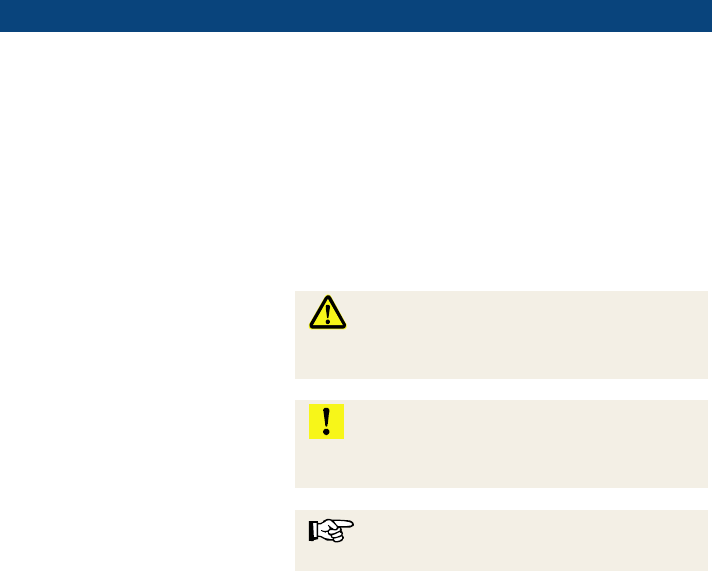
1.2 Notes
WARNING!
Not following this warning can cause injury or
death.
ATTENTION!
Not following this note can cause permanent
damage to the device.
NOTE!
Useful information
1.3 Intended Use
The Wöhler DP 600 Leakage Tester controls the
tightness of all exhaust gas systems listed in EN
1443 by measuring the air flow required to main-
tain the test pressure level.
The instrument is also suitable for the 4 Pa test
(standard method and enhanced method) accord-
ing to the DVGW (German Association of Gas and
Water Engineers) sheet G 625 (2009). The 4 Pa
Pressure Test is a simple control of the under-
pressure limit 4 Pa which informs whether there is
sufficient combustion air supply or not. No auxilia-
ry measuring instrument will be necessary.
The device is suitable to control the tightness of
fireplaces. The DP 600 measurement is based on
the approval principles for non-roomsealed heat-
ing appliances, published by the German Institute
for Building Technology (Deutsches Institut für
Bautechnik) in July 2002.
Do not use the device for any other use than set
out in this manual.
General Information
5
1.4 Components
Device
Components
Wöhler DP 600
Leakage Tester
Power cable
Adapter 0,3
Adapter 3,0
1.5 Transport
ATTENTION!
Improper transport can harm the instrument.
Always transport the instrument in the provided
carrying case in order to prevent damage.
The case is included in the sets and also can be
bought separately.
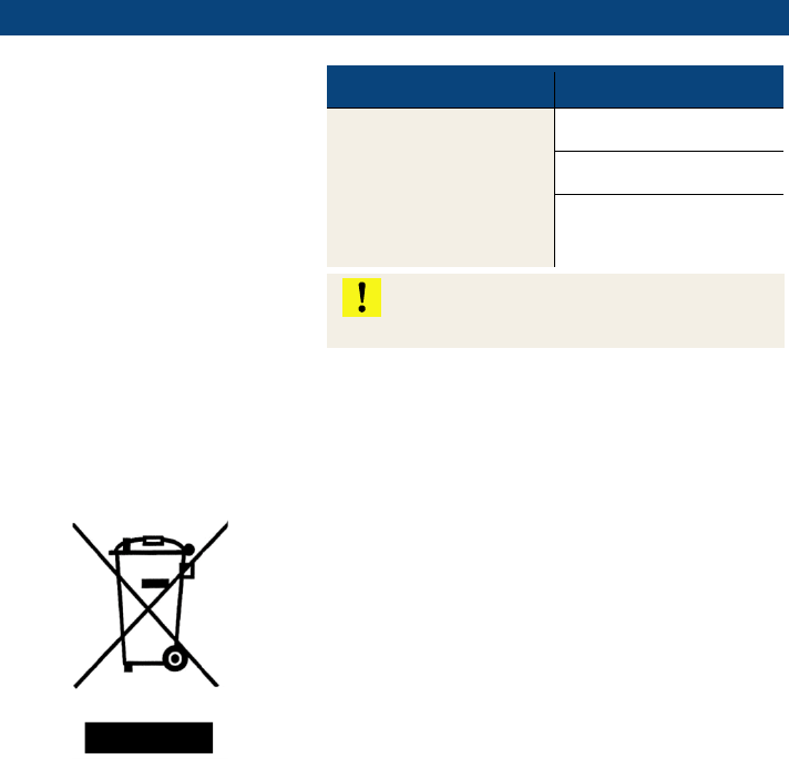
1.6 Information on disposal
Electronic equipment does not belong into domes-
tic waste, but must be disposed in accordance
with the applicable statutory provisions.
You may hand in any defective batteries taken out
of the unit to our company as well as to recycling
places of public disposal systems or to selling
points of new batteries or storage batteries.
1.7 Manufacturer
Wöhler Technik GmbH
Wöhler Platz 1
33181 Bad Wünnenberg
Tel.: +49 2953 73-100
Fax: +49 2953 7396-250
Technical Data
6
2 Technical Data
Pressure
Range
0 to 7000 Pa
Resolution
0,1 Pa from
0,0 to 900,0 Pa
1 Pa from 900 Pa on
Accuracy
± 0,5 Pa, ± 2,5 % of
reading
NOTE!
The volume flow here indicated
refers to a tension of 230V. If
the tension is lower, the volume
flow will be reduced.
NOTE!
Volume flow measurement is
possible up to a maximum
differential pressure of
± 5000 Pa.
Volume flow without adapter
Range
0,0 to 200,0 Nm³/h
Resolution
0,1 Nm³/h
Accuracy
± 2,5 Nm
3
/h,
± 5 % of reading
Volume flow with adapter 3,0
Range
0,00 to 10,00 Nm³/h
Resolution
0,01 Nm³/h
Accuracy
± 0,05 Nm
3
/h,
± 5 % of reading
Volume flow with adapter 0,3
Range
0,10 to 18,00 NL/min
(0,006 to 1,080 m
3
/h)
Resolution
0,01 NL/min
Accuracy
± 0,05 NL/min,
± 5 % of reading
Technical Data
7
General technical data
Power supply
110 to 230 V,
50 to 60 Hz
Operation temperature
5 °C to 40 °C
Storage temperature
-20 °C to +50 °C
Size
33 x 36 x 15 cm
Weight
9,2 kg
Component explanation
8
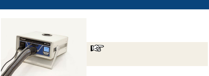
3 Component explanation
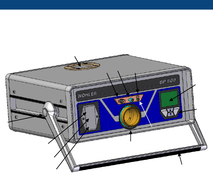
3.1 Device
Fig. 1: Overview
1 On/Off switch
2 Power supply connection
3 Fuse switch
(Microfuse T10, 250 V)
4 Pressure connection (over-
pressure) with plug-in con-
nector
5 Differential pressure con-
nector (under pressure) with
tube connector
6 Infrared interface for Wöhler
TD 100.
7 USB port
8 Color display
9 Keypad
10 Air connection - over pressure (without
adapter)
11 Air connection - under pressure
12 Pivoting carrier
13 Pressure point for adjusting the carrier
(on both sides)
1
2
3
4
5
6
7
8
9
11
12
13
10

Component explanation
9
3.2 Adapter
ATTENTION!
The serial number of the adapter must match the serial number of the Wöhler DP 600.
(The serial number can be found on the silver sticker on the adapter and on the back-
side of the Wöhler DP 600.)
Fig. 2: Adapter 0,3
The Wöhler DP 600 features a wide measuring
range of the volume flow. Two different adapters
are necessary to guaranty the specified accuracy
of the volume flow measurement.
NOTE!
The instrument does not recognize automatically if
an adapter is inserted or not.
The adapter 0,3 has to be inserted into the air
connection (over pressure) (Fig. 1, part 10), when
exhaust gas systems class P + H have to be con-
trolled with small volume flows.
Fig. 3: Adapter 3,0
The adapter 3,0 has to be inserted into the air
connection (over pressure) (Fig. 1, part 10) when
measurements with volume flows 0,00 to 10,00
Nm³/h have to be done, for example for a stove
test.
No adapter is used for measurements with volume
flows 0 to 200 m
3
/h at exhaust gas systems class
N.
Component explanation
10
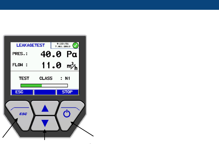
3.3 Display
The Wöhler DC 600 has a color display with a di-
agonal of 6 cm. The OLED
-technology allows read-
ing the display from almost any angle of view.
The Wöhler DP 600 is operated using four multiple
function keys.
Escape
Scroll/change values
OK / NEXT / STOP
Component explanation
11
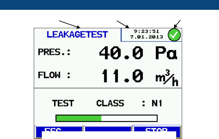
The display is divided into a status, a menu and a
readings segment.
The currently selected mode or menu is shown in
the left status segment.
-
Date and time and the system diagnosis status
are shown in the status segment on the right.
The readings segment displays the readings or the
menu items.
The menu segment is situated at the bottom of the
display. It consists of three soft keys.
Measuring mode
Date and time
System diagnosis status
Fig. 4: Wöhler DP 600 Display

Component explanation
12
3.4 Necessary accessories
Probes, tubes, sealing bladders and sealing elements are not included, but can be pur-
chased as accessories. As there are many different
types of exhaust gas systems, in
specific cases it may be necessary to adapt the sealing elements.
NOTE!
Use the Wöhler sealing elements with the blue marking for your measuring tasks.
3.4.1
Sealing Set for chimneys Class N
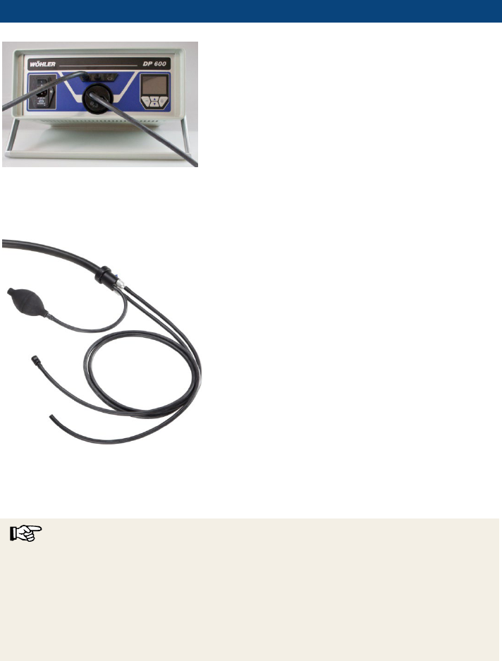
Fig. 5: Sealing Set Class N
The Sealing Set Class N is necessary for meas-
urements on chimneys Class N. The set includes
a Probe Class N (1), an extension tube (2), a
straight sleeve and an angled sleeve, an air tube,
4 m (3), a pressure tube 4 m (4) and different
sealing elements.
The user can purchase Sealing Elements of many
different forms and sizes. Nevertheless it may be
necessary to adapt the Sealing Element to the
exhaust gas installation or the chimney. In this
case we recommend to use Sealing Elements that
can be cut individually. (see accessories).
3.4.2 Sealing Set for chimneys Class P, M + H
Fig. 6: Sealing Set Class P, M + H
For the control of exhaust gas systems of class P
M and H two hoses, a Sealing Bladder with gas
lead through, a Sealing Bladder without gas lead
through and a ball pump are necessary.
NOTE!
The necessary accessories can be purchased in a
set.
Generally exhaust gas systems of class P, M and
H are round stainless steel tubes. Sealing round
exhaust ducts with a Sealing Bladder is easy and
safe. Different Sealing Bladders up to Ø 600 mm
can be purchased.
Nevertheless, exhaust gas systems can have
many different forms, so that it may be necessary
to create a sealing system for the installation to be
controlled.
1
2
3
4

Component explanation
13
NOTE!
Sealing systems adapted to a certain installation
must fulfill many requirements. All questions con-
cerning the sealing should be addressed to Wöh-
ler (see manufacturer's address in chapter 1.7).
When controlling exhaust gas systems of class H,
the measurement is done with a test pressure of
5000 Pa. Therefore it is absolutely necessary to
fix the Sealing Bladder so that it cannot be moved
or blown. For this purpose, the Sealing Bladder
can be fixed at the beginning or the end of the test
section with a reinforced adhesive tape or with
load securing nets.
The result of the measurement will only be exact,
when the position of the Sealing Bladder has not
changed during the measurement.
•
Mark the position of the Sealing Bladder with a
pencil before starting the measurement.
Component explanation
14
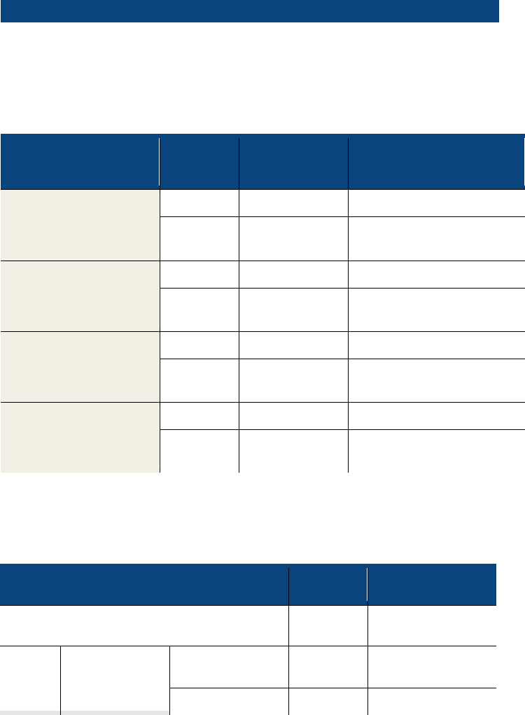
3.5 Function
The Wöhler DP 600 controls the tightness of exhaust ducts and chimneys. A menu ena-
bles the user to select between the different installation classes. The Wöhler DP 600
regulates automatically the pressure which is necessary to control the flue gas systems
classes P,
M and H and N and determines the leakage rate automatically.
Description of the
exhaust gas system
Classifica-
tion Type
Test pressure
Maximum allowable
leakage rate per m
2
inner surface
Exhaust gas system
negative pressure
operation
(chimney)
N1
40 Pa
7,20 m
3
/h
N2
20 Pa
10,80 m
3
/h
Exhaust gas system
low overpressure opera-
tion
(Exhaust pipe)
P1
200 Pa
0,36 l/min (0,022 m
3
/h)
P2
200 Pa
7,20 l/min (0,432 m
3
/h)
Exhaust gas system
middle overpressure
operation
M1
1500 Pa
0,36 l/min (0,022 m
3
/h)
M2
1500 Pa
7,20 l/min (0,432 m
3
/h)
Exhaust gas system
high pressure operation
(block heat and power
plant)
H1
5000 Pa
0,36 l/min (0,022 m
3
/h)
H2
5000 Pa
7,20 l/min (0,432 m
3
/h)
Table of the classes of exhaust gas systems according to EN 1443 (DIN 18160)
The Wöhler DP 600 can also be used to control the tightness of a stove. According to
the approval guidelines concerning the evaluation of room sealed heating applications
the following requirements apply for the tightness of the heating application with the
ne
cessary connecting pipe for the combustion air and the connecting piece.
Description of the exhaust gas system
Test
pressure
Maximum allowa-
ble leakage rate
solid-fuel fireplaces 10 Pa 2,0 m
3
/h
oil fire-
places
Fireplaces with
connections
completely
air flushed
50 Pa 5,0 m
3
/h
partly air flushed
50 Pa
1,0 m
3
/h
Component explanation
15
fireplace only
completely
air flushed
50 Pa 3,0 m
3
/h
Partly air flushed
50 Pa
0,6 m
3
/h
With the Wöhler DP 600 Leakage Tester the 4 Pa-test to control the underpressure limit
4 Pa can be performed. The 4 Pa test controls if there is a sufficient combustion air sup-
ply according to the DVGW (German Association of Gas and Water Engineers) Note G
625. No additional measuring instrument will be necessary for the 4 Pa test. The test
measures the differential pressure between the room and the ambient air during the
operation of the fireplace (standard method) or when the theoretically required combus-
tion air is withdrawn (enhanced method).
Component explanation
16
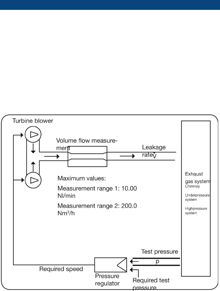
3.5.1 Measurement principle
The seal on exhaust gas systems is measured by
inflating the line to a constant overpressure and
measuring the volume flow required to maintain
the overpressure.
The following diagram shows the principle of the
measurement configuration. The volume flow
generated by means of two turbine blowers is fed
into the sealed exhaust gas system by means of a
hose. As a result of incoming air, the pressure in
the exhaust system rises. This pressure is fed
back to the measuring device via a second hose.
The turbine blowers are regulated by comparing
the preset test pressure with the actual test pres-
sure in the exhaust gas system.
Fig.
7: Measuring principle Wöhler DP 600
Menu navigation
17
4 Menu navigation
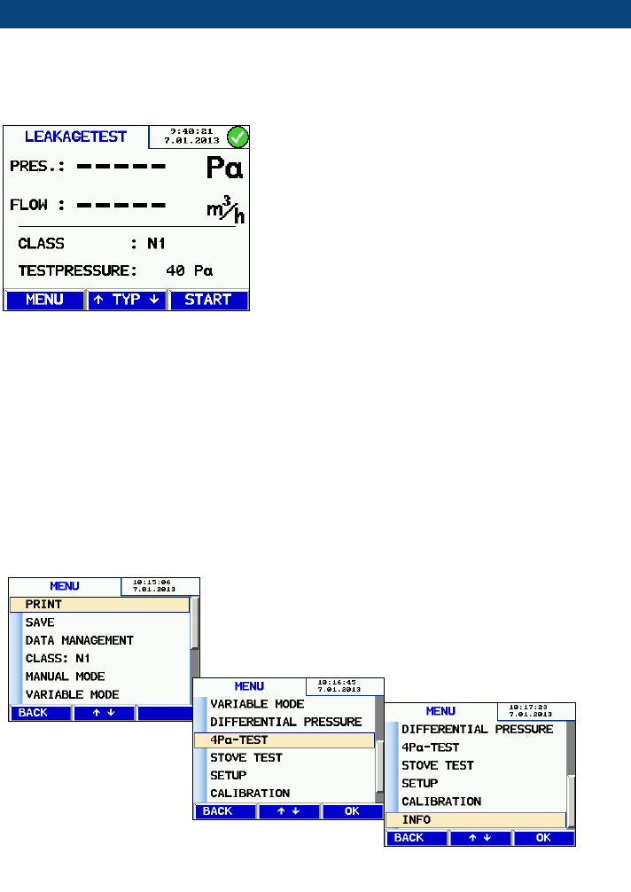
4.1 Main menu
Fig.
8: Opening screen
Immediately after the Wöhler DP 600 has been
switched on, the version and afterwards the open-
ing screen are displayed (see figure on the left).
To activate the main menu, press menu when the
opening screen is displayed. In the main menu, all
submenus and applications can be activated. The
following menus are available:
- Print
- Save
- Data management
- Exhaust Gas System Class
- Manual Mode
- Variable Mode
- Differential Pressure
- 4 Pa - Test
- Stove Test
- SETUP
- Calibration
- Info
Fig. 9: Main menu
Menu navigation
18
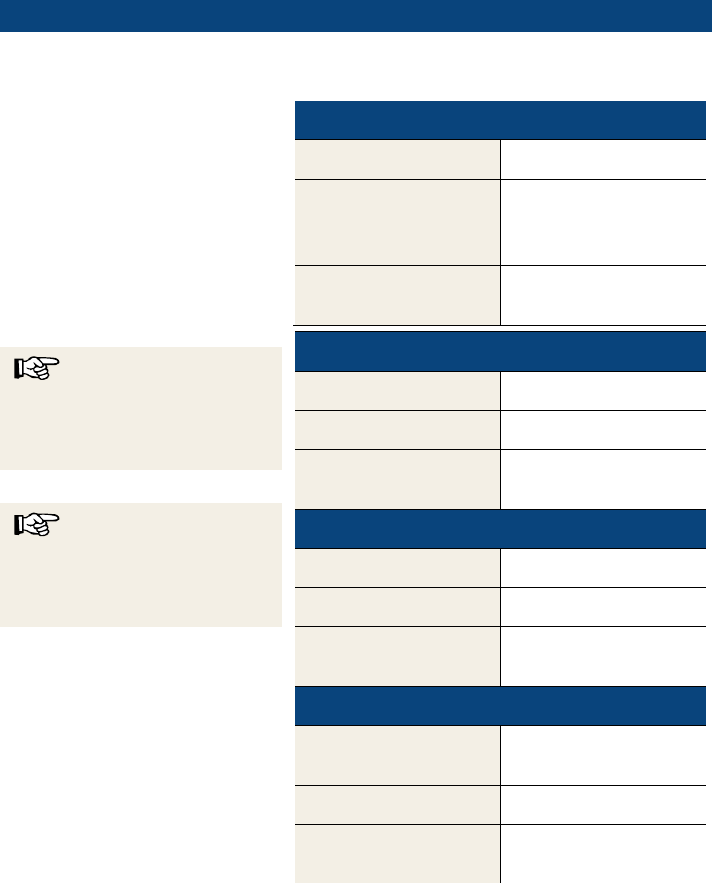
4.2 Overview sub menus
Menu
Sub menus
Contents and
Notes
Print
Transfer data to the
thermo printer via an
infrared port
Save
New customer > create a new
customer
Relate the measured
data to a customer and
save
Data management
Print
Print the saved meas-
urement results later
Delete riser
Delete a single riser
Delete customer
Delete all records of a
single customer
Delete all customer records
Exhaust Gas System
Class
N1: 40PA
Select the exhaust gas
system class
(The most common
classes N1, M1, P1 and
H1 can be selected
directly in the leakage
test menu).
P1: 200 Pa
M1: 1500 PA
H1: 5000 Pa
N2: 20 Pa
M2: 1500 Pa
P2: 200 Pa
H2: 5000 Pa
Menu navigation
19
Manual Mode
Same as Leakage Test
The user selects the
adapter and controls
the volume flow.
Intended for
experienced users
only.
Variable Mode
Same as Leakage Test
The user selects the
adapter and controls
the volume flow and
selects the limit value.
Intended for
experienced users
only.
Differential Pressure
Diagram
Printing out measurement records
Diagram: differential
pressure during the
last four minutes
(It is not possible to save the dia-
gram)
4 PA-Test
Standard method
Control if sufficient
supply of combustion
air is assured.
Enhanced method
Stove Test
Same as Leakage Test class N
Measures the leakage
rate of the tested
stove
Always with Adapter
3,0
Menu navigation
20
SETUP
Date
Time
Time
Brightness
Backlight
Units
Pa, hPa, mbar,
mm/H
2
O, in/Wc
Auto Mode
Select between normal
mode or the last mode
that was especially
configured.
Controller
Normally the user
should not change this
parameter.
Factory Reset
Reset all settings to
their factory default.
Printer logo
Enter the logo of the
society.
Calibration
Calibration menu
locked by a keyword
Only authorized Ser-
vice points may cali-
brate the device.
Info
Cycles
Hours
Date of manufacture
Date of calibration
Firmware version
Leakage test of exhaust gas systems
21
5 Leakage test of exhaust gas systems
WARNING!
Before starting the measurement, switch off the heating system!
5.1 Installing the device
ATTENTION!
Before measuring with the device take it out of the case and place it in a free position.
If you work with the device while it is in the case, the heat development will lead to dys-
functions and a safety switch off..
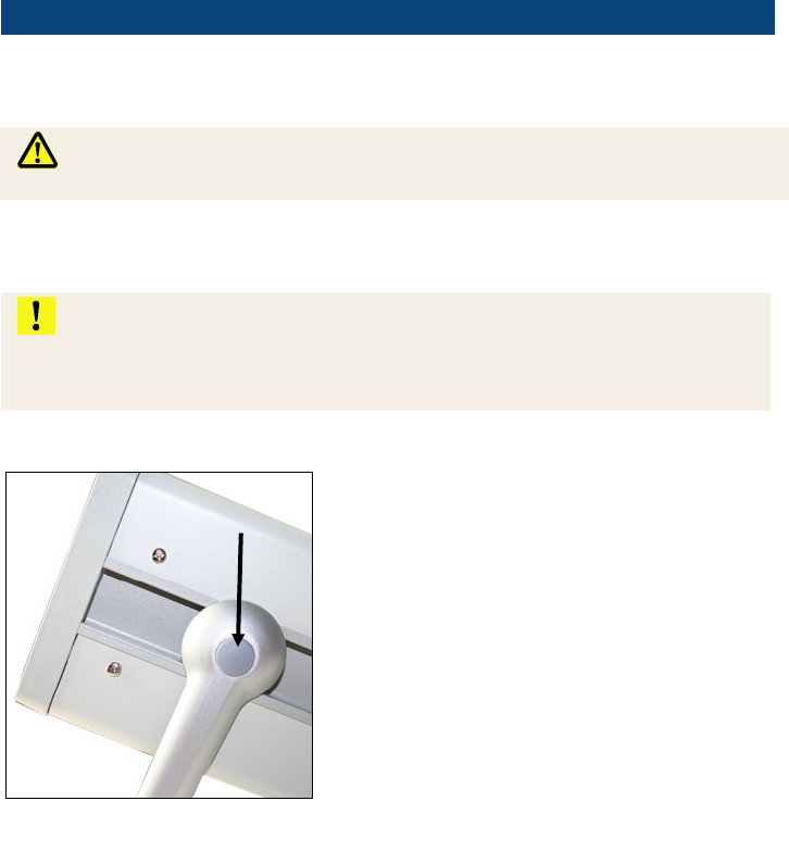
• Place the Wöhler DP 600 on a dry and flat
surface and ensure a secure position.
•
Adjust the carrier to a position that is favorable
for you. Press the two pressure points (Fig. 1,
point 13) to change the position.
Four positions of the carrier are possible.
• Afterwards connect the probes and hoses
which are necessary for the measurement and
seal the test object as described in the follow-
ing chapters.
Fig. 10: Pressure point for adjusting the
carrier
Leakage test of exhaust gas systems
22
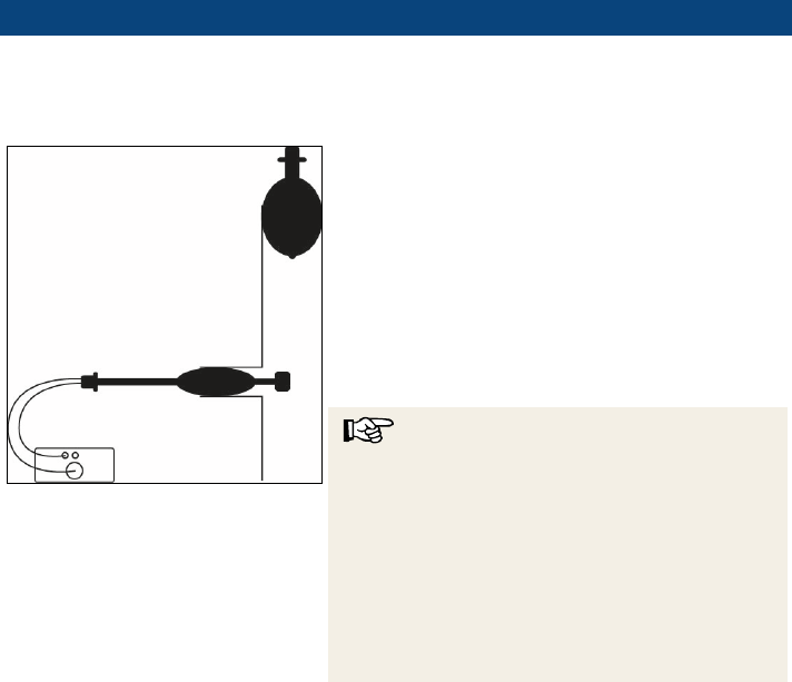
5.2 Preparing the control of an exhaust gas system class P, M or H
You need a Sealing Set Class P
, M + H, see chapter 3.4.2
• Seal the top of the exhaust duct with a Sealing
Bladder. The Sealing Bladder must be without
gas lead through and its nominal size must
match with the diameter of the exhaust gas
system.
•
Insert the Sealing Bladder with a double gas
lead through into the exhaust gas system.
Plug the ball pump on the smallest connector
and inflate the Sealing Bladder until it is fixed
in the nozzle. Remove the ball pump.
NOTE!
There may be considerable amounts of conden-
sate in exhaust pipes. This is particularly the case
in flexible exhaust pipes due to the larger surface
area. Therefore we recommend to first set the up-
per sealing bladder. When setting the lower seal-
ing bladder, make sure that it is not positioned
directly in the condensate and that no condensate
can settle on the bladder. Otherwise, the unit may
be damaged by condensation penetrating the
bubble.
•
Fig. 11: Schematic drawing of an ex-
haust duct (stainless steel)

Leakage test of exhaust gas systems
23
5.2.1 Sealing with the Sealing Set Compact, Type P, M + H
Positioning of the upper sealing bladder without gas
leed-through
Fig
. 12: Positioning the upper sealing
bladder with
telescope set and viper
The Sealing Set Compact contains a telescope
set with which the upper bladder can be placed.
This procedure is particularly practical if there is
no upper inspection opening and the inspection
opening is not accessible.
Fig
. 13: Extension hoses (1) and push
rod
(2)
To position the upper sealing bladder with tele-
scope set you need
• Extension hoses (3 extension hoses 2.5
m, 5 m and 10 m are included in the
Sealing Set Compact).
• Push rod (included in the Sealing Set
Compact)
• Viper or GFK rod
Proceed as follows:
Fig
. 14: Screwing the Push rod onto the
viper
• Screw the push rod onto the connecting
thread of the viper or rod.
1
2

Leakage test of exhaust gas systems
24
Fig
. 15: Adapter M5 / M10
Note!
The push rod has a M5 thread. If a viper or rod
with M10 thread is used, the thread adapter in-
cluded in the scope of delivery must be used.
Fig
. 16: Viper connected to the sealing
bladder
with gas lead through
• Insert the other end of the push rod into the
sealing bladder connector.
Fig
. 17: Connection for extension hose
marked with arrow
• Extend the bladder tube to the desired length
using the extension tubes.
NOTE!
The extension hoses can be screwed together as
required.
Leakage test of exhaust gas systems
25
Fig
. 18: Positioning the upper Sealing
Bladder „Compact
” without gas lead
through with the telescopic set.
• Position the sealing bladder at the top of the
exhaust pipe.
NOTE!
It is easier to push the bladder when it is wet. If
necessary, moisten before pushing.
•
Connect a pump to the hose and inflate the
bladder until it is firmly seated in the pipe.
•
Pull the the push rod out of the pipe.
•
Put the hose of the upper sealing bladder
completely in the exhaust pipe so that the
lower sealing bladder can be placed.
Leakage test of exhaust gas systems
26
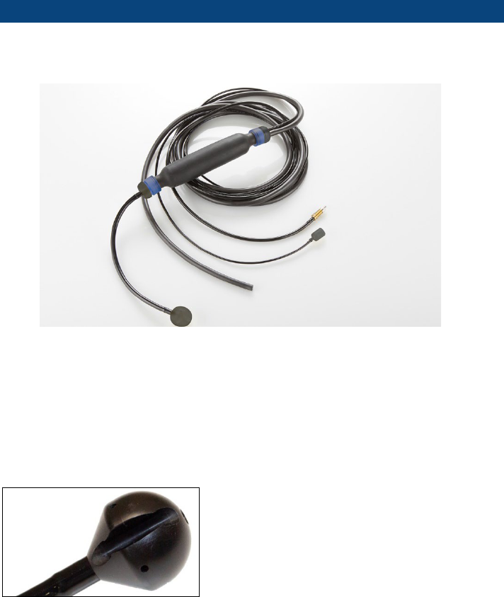
Connection and positioning of the lower sealing bladder with gas lead
through
Fig
. 19:
Sealing bladder compact with gas lead through for sealing the exhaust pipe from
below and for connection to the Wöhler DP 600
1
Connection for air pump and valve to discharge the air
2
Pressure hose with connection coupling
3
Air hose
4
Filler (impedes penetration of condensate)
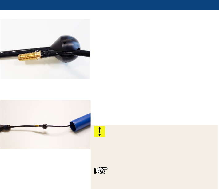
Fig
. 20: Filler of the lower sealing bladder
The filler (part 4) has a slot through which the
extension hose of the upper sealing bladder can
be passed.
1
3
4
2
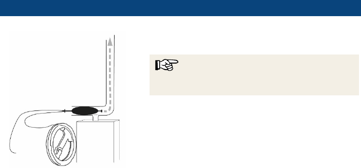
Leakage test of exhaust gas systems
27
Fig.
21
: Filler of the lower sealing bladder
with
extension hose of the upper sealing
bladder
• Clamp the end of the extension hose of the
upper sealing bladder into the slot of the filler.
Fig.
22: Connection of the two sealing
bladders
• Push the lower sealing bladder together with
the extension hose of the upper bladder into
the exhaust pipe.
ATTENTION!
Take care not to place the bladders in front of
sharp edges.
Make sure that the filler (4) is not placed in con-
densate.
NOTE!
After the measurement, the extension tube with
the bladder can easily be pulled out again.
•
Connect an air pump to port 1 (see Fig. 19:
Sealing bladder compact with gas lead
through for sealing the exhaust pipe from be-
low and for connection to the Wöhler DP 600)
and inflate the bladder until it is firmly seated
in the pipe.
Leakage test of exhaust gas systems
28
Fig.
23: Connection of the pressure
tube and the air tube to the Wöhler
DP 600
Fig.
24
: Connection of the ball pump,
the pressure tube and the air tube
• Connect the hoses to the Wöhler DP 600
as follows:
-
Place the adapter 0,3 in the air connec-
tion (over pressure) (Fig. 1, part 10).
-
Plug the air tube on the connector of the
adapter.
-
Plug the free end of the air tube to the
connector of the Sealing Bladder marked
by an arrow that points to the exhaust gas
system.
-
Plug the pressure tube on the overpres-
sure socket (+) (Fig. 1, position 4).
-
Plug the free end of the pressure tube to
the connector of the Sealing Bladder
marked by an arrow that points away
from the exhaust gas system.
NOTE!
Fix the Sealing Bladder so that it cannot get out of place during the measure-
ment, especially when measuring an exhaust gas system of class P with a di-
ameter > 150 mm and when measuring an exhaust gas system of class H.
The result of the measurement will only be correct, when the position of the
Sealing Bladder has not changed during the measurement. You can easily
control the position of the Sealing Bladder in the exhaust gas duct by marking
it with a pen before the measurement.
Leakage test of exhaust gas systems
29
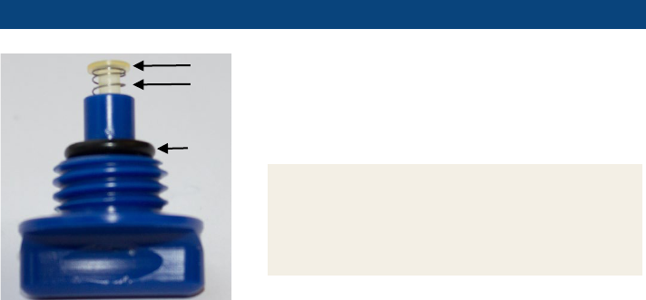
Fig.
25: Drain valve with O-ring (1),
compression spring (2) and valve
plug (3)
• - If the drain valve has been unscrewed
from the sealing set, make sure that the
valve parts in the adjacent illustration are
complete when screwing them in. Only
then can the valve seal reliably.
NOTE!
In particular, the small valve plug must not be
missing. It often gets stuck when unscrewing
the valve and can then be blown out of the
sealing set with the pump.
1
2
3
Leakage test of exhaust gas systems
30
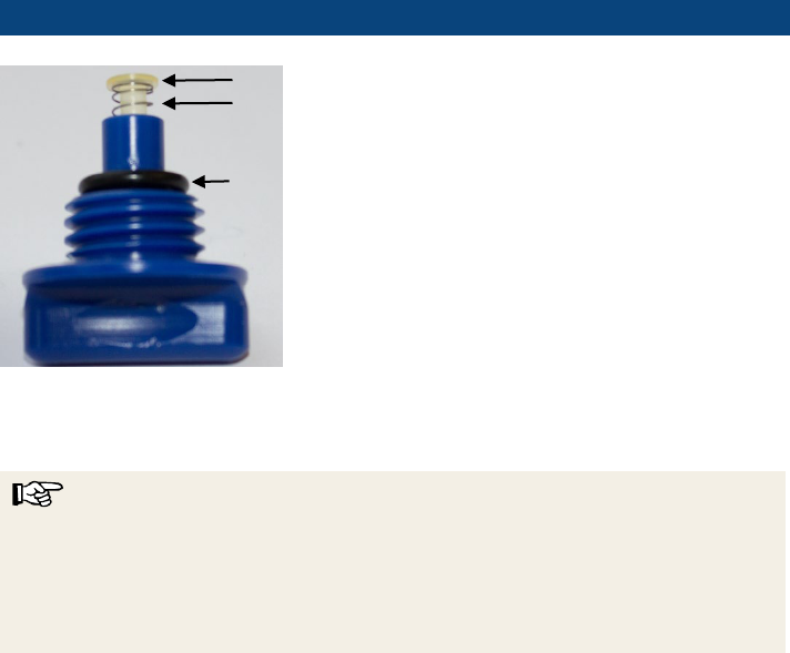
Fig
. 26: Drain valve with O-ring (1),
compression spring (2) and valve plug (3)
NOTE
For type P measurements on larger exhaust systems (diameter > 150 mm) and all type
M and H measurements, ensure that the sealing bubbles are secured against slippage
during the measurement. A correct measurement result can only be achieved if the po-
sition of the sealing bubble does not change during the measurement. For easy check-
ing, the position of the sealing bubble in the exhaust pipe should be marked with a
pencil before measurement.
1
2
3
Leakage test of exhaust gas systems
31
5.3 Preparing the control of an exhaust gas system class N
You need a Sealing Set Class N, see chapter
3.4.1.
5.3.1 Assembling the Probe Class N
Fig. 27: Assembling the Probe Class N
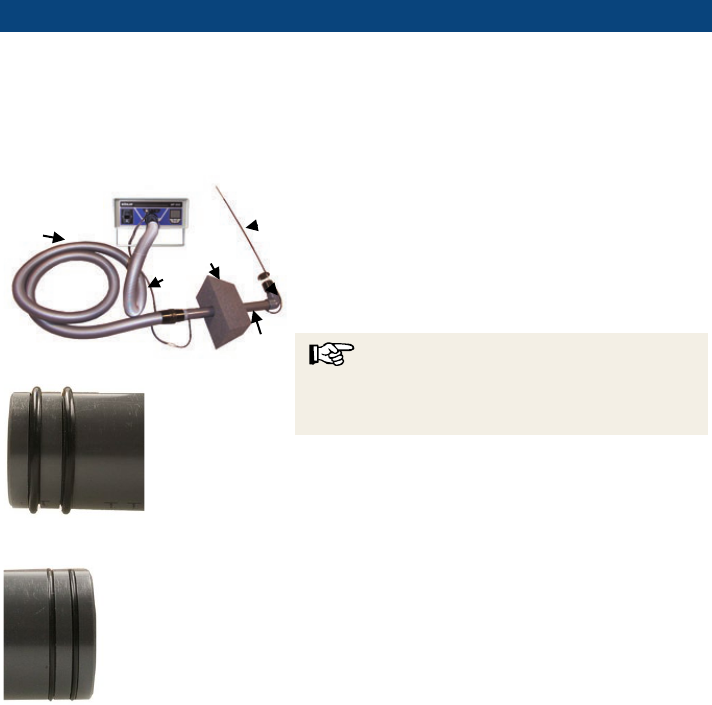
Fig.
28: Extension pipe end with wide O-
ring
- hose connector
Fig.
29: Extension pipe end with narrow
O
-ring - probe connector
• Plug a Sealing Element with hole (1) on the
extension pipe (2).
•
Connect the probe (3) to the elbow connector
(4).
•
Connect the elbow connector via the exten-
sion pipe (2) to the plastic hose (5).
NOTE!
Plug the hose to the end with the wide O-rings
and the elbow connector to the end with the nar-
row O-rings.
1
2
3
4
5
6
Leakage test of exhaust gas systems
32
Fig.
30: Hoses and cable connected to
the measuring instrument for the leakage
test class N: Mains cable, pressure hose
and plastic hose
• Plug the free end of the plastic hose (5) to the
air connection (over pressure) (Fig. 1, part
10).
NOTE!
Do not install any adapter when controlling ex-
haust gas systems class N.
Leakage test of exhaust gas systems
33
Fig.
31: Probe connected to the exten-
sion pipe.
Fig.
32
: Extension hose connected to the
pressure hose.
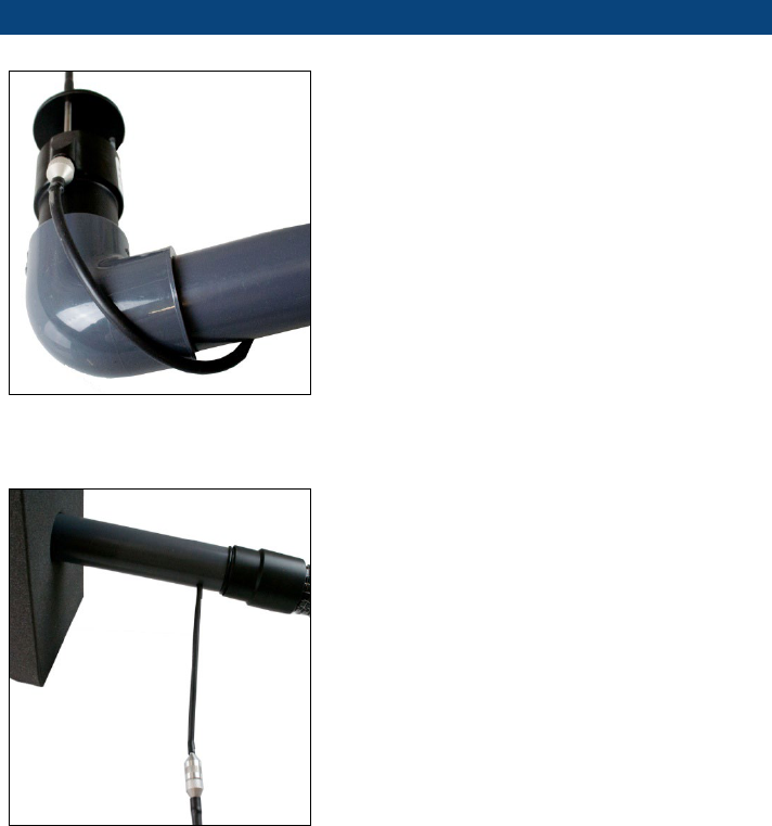
• There is a small hose fixed to the upper end of
the extension pipe. Plug the connector of that
hose to the jack of the probe, see figure 18.
•
Plug the hose fixed to the bottom of the exten-
sion pipe to the pressure hose that is con-
nected to the DP 600, see fig. 19.
•
Connect the pressure hose (6) to the over-
pressure socket (+) (Fig. 1, position 4).
Leakage test of exhaust gas systems
34
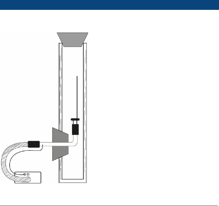
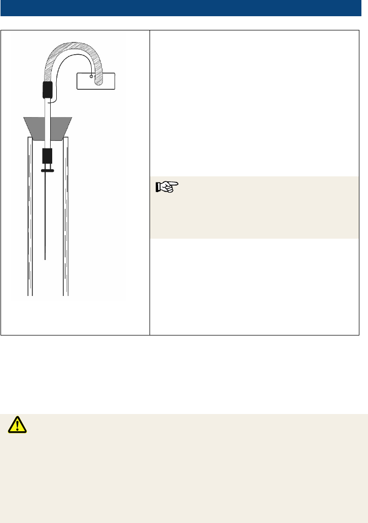
5.3.2 Installation of the probe in the exhaust gas system (chimney)
Fig.
33: Schematic drawing of a brick
lined chimney
• Carefully insert the probe through the cleaning
aperture into the chimney, see schematic
drawing.
•
Take care that the Sealing Element seals the
cleaning aperture totally.
•
Seal the top of the chimney with a sealing
element without hole.
If there is not enough space to install the probe into the chimney as shown in Fig. 33:
Schematic drawing of a brick lined chimney
there are three other possibilities to install
the probe. In the following examples, always use the straight sleeve instead of the an-
gled sleeve
(The straight sleeve forms part of the scope of delivery.)
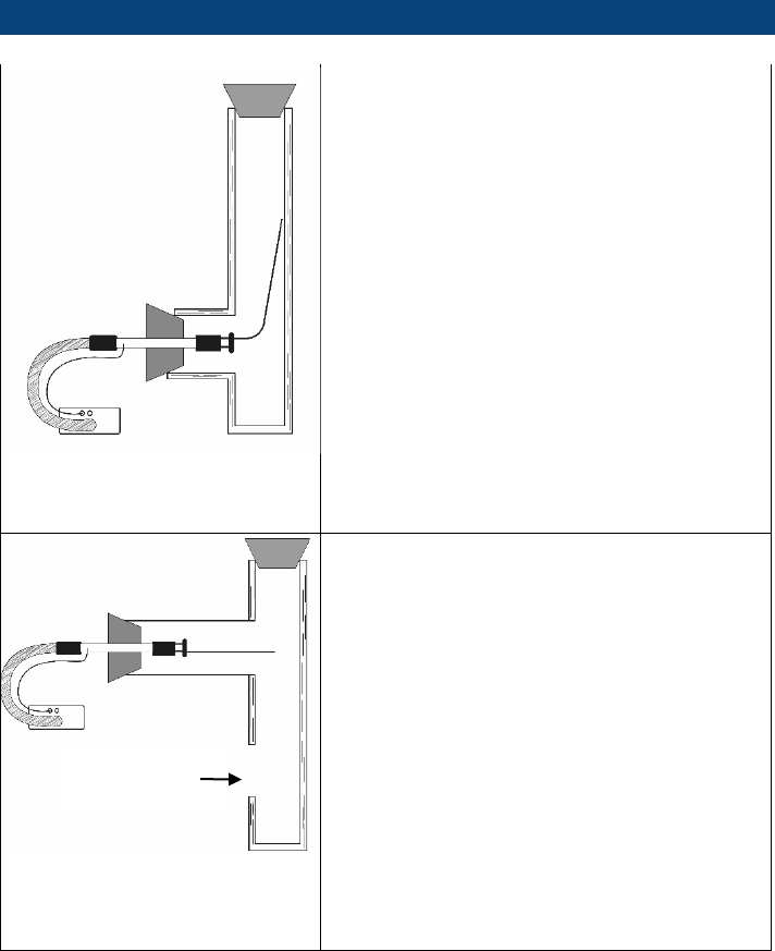
Leakage test of exhaust gas systems
35
Fig
. 34: Installation of the probe through
the chimney door
, bending the probe.
• Connect the probe to the extension pipe via
the straight sleeve (see Fig. 31).
•
Carefully insert the probe through the cleaning
aperture into the chimney bending the probe
at 90°
•
Take care that the Sealing Element seals the
cleaning aperture totally.
•
Seal the top of the chimney with a sealing
element without hole.
Fig
. 35: Installation of the probe through
the
furnace connection tube using the
straight sleeve
If the furnace is not yet connected to the chimney,
the probe can be installed into the chimney
through the furnace connection tube. Proceed as
shown in
Fig. 35.
•
Connect the probe to the extension pipe via
the straight sleeve (see Fig. 31).
•
Carefully insert the probe through the furnace
connection tube into the chimney.
•
Take care that the Sealing Element seals the
aperture totally.
•
Seal the top of the chimney with a sealing
element without hole.
•
Close the chimney door.
close
chimney door
Leakage test of exhaust gas systems
36
Fig
. 36: Installation of the probe from the
roof
through the
chimney orifice using the
straight sleeve
The probe can also be installed from the roof
through the chimney orifice. This method is suita-
ble to test the density of the whole system with
furnace connection and chimney door.
•
Connect the probe to the extension pipe via
the straight sleeve (see
Fig. 31).
•
Carefully insert the probe from the top through
the furnace orifice tube into the chimney.
•
Take care that the Sealing Element seals the
orifice totally.
NOTE!
If it is not possible to place the Wöhler DP 600 on
the roof, use extension hoses: Extension hose
(air) 3,75 m (art. 50676) and Pressure hose 10m
(art. 4250).
5.4 Turning on the Wöhler DP 600
• After all necessary accessories have been connected to the Wöhler A 600 as de-
scribed, connect the power cord to the instrument and plug it into an outlet.
WARNING!
Risk of electrical shock!
The Wöhler DP 600 is supplied with a voltage of 230 VAC. Coming in contact with live
parts can be lethal.
Never touch the power supply with wet hands!
Do not unplug the power supply by pulling the cable!
Do not use the device when the voltage requirements of the device and the supply do
not match!
Leakage test of exhaust gas systems
37
• Switch on the Wöhler DP 600.
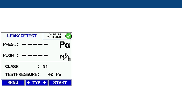
5.5 Leakage test in normal mode
Fig.
37: Leakage test of exhaust gas
installations class N1
5 seconds after the device has been switched on
the version is displayed.
After that the display "Leakage test" appears.
Leakage test of exhaust gas systems
38
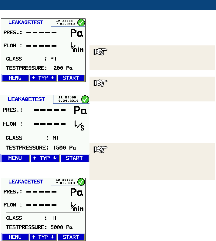
Fig.
38: Leakage test of an exhaust gas
installation class P1
Fig.
39: Leakage test of an exhaust gas
installation class P1
Fig.
40 Leakage test of an exhaust gas
installation class H1
• Press the arrow keys to select the class.
In this mode, the standard installations class N1,
P1, M1 and H1 can be selected.
NOTE!
All other
installation classes can be selected in the
menu "Class"
NOTE!
In normal mode, the last installation class selected
will be displayed.
The necessary test pressure according to EN
1443 will be indicated depending on the selected
installation class.
Furthermore, the indicated volume flow will
change automatically to the correspondent unit.
NOTE!
Make sure that the correct adapter has been in-
stalled (see chapter 3.2
). The instrument does not
recognize automatically if an adapter has been
installed or not.
Leakage test of exhaust gas systems
39
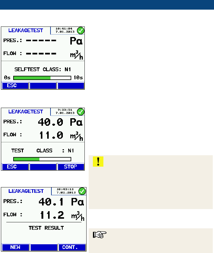
Self test
Fig.
41: Self test
• Press "Start" to start the measurement.
The Wöhler DP 600 will automatically start a self
test to control the internal probes. The self test
takes 10 sec. The test also checks if the exhaust
gas system is at normal pressure and if there are
any pressure variations. After that the Wöhler DP
600 will automatically start the measurement.
Display during the measurement
Fig.
42: running measurement
Fig.
43: Result display
Now the Wöhler DP 600 creates the test pressure.
When the test pressure is reached, the measure-
ment will start automatically. During the meas-
urement the currently measured volume flow is
indicated. As soon as the readings have stabi-
lized, the Wöhler DP 600 will perform the meas-
urement automatically and finish the test after
that.
ATTENTION!
After measurements of Class P and H the note
“Test Finished” will appear.
Before switching
off the device, unplug the air tube to prevent
that condensation water is pressed from the ex-
haust gas installation into the measuring instru-
ment.
The result is shown in the display.
NOTE!
The result corresponds to the leakage rate of the
exhaust gas system.
• Press New to return to the measurement
menu and start a new measurement where
required or
•
Press Cont. (continue) to bring up the evalu-
ation.
Leakage test of exhaust gas systems
40
Evaluation
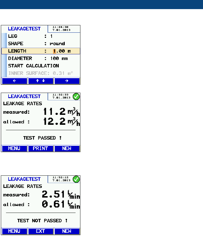
Fig.
44: Entering the cross section area:
• Enter the cross section area. Proceed as
follows:
With the up and down keys go to the parame-
ter to be changed, confirm your selection with
the right key and enter the value with the up
and down keys.
Shape, length and diameter can be entered for
three sections. The Wöhler DP 600 will calculate
the cross section area automatically.
•
Select Start evaluation and confirm with OK.
The measured leakage rate, the maximum al-
lowed leakage rate according to EN 1443 and an
evaluation (TEST PASSED or TEST NOT
PASSED) will be displayed.
For measurements of exhaust gas installations of
class P the following applies:
If the measured leakage rate is higher than the
allowed leakage rate, an additional measurement
(extended procedure) can be performed.
•
To do so, press Ext.
The Wöhler DP 600 will now blow an airflow cor-
responding to the permissible leakage rate into
the exhaust gas system and measure the pres-
sure that the air has created in the exhaust gas
system. The result will be shown in the display.
The user has the following possibilities now:
Fig. 45: Evaluation of the measure-
ment results (Class N)
Fig. 46: Evaluation of the measure-
ment results (Class P or H)
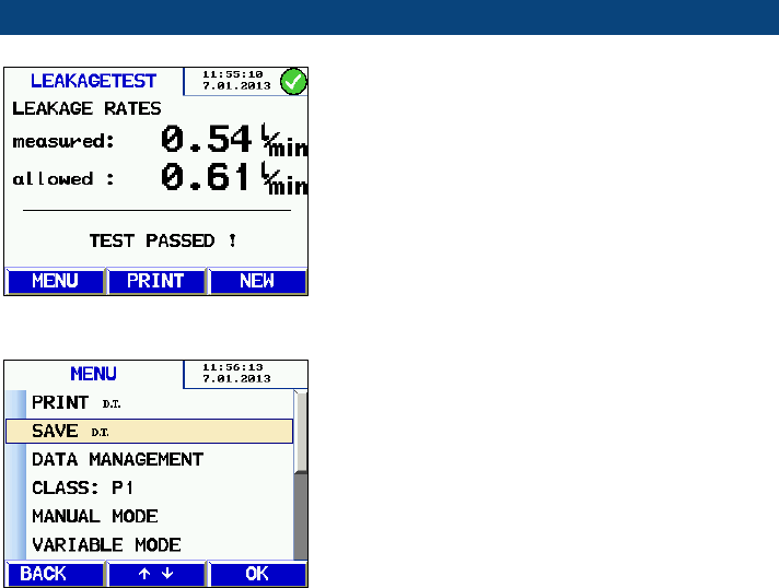
Leakage test of exhaust gas systems
41
• Press Menu to return to the measuring menu
again.
•
Press New to start a new measurement.
•
Press PRINT to print the measurement result
on the Wöhler TD 100 Thermoprinter.
•
Press Menu > SAVE to save the measure-
ment (see chapter.
10).
Fig.
48: Main menu after the density test
has been performed.
• After the measurement; D.T. (density test) will
appear next to the submenus Print and Save.
So it is obvious that the density test has al-
ready been done.
Fig. 47: Evaluation of the measure-
ment
results (exhaust gas system OK)
Leakage test of exhaust gas systems
42
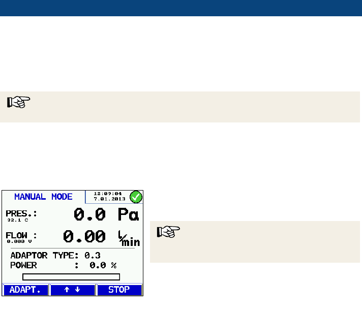
5.6 Manual Mode
In the manual mode, the measurement can be done without an automatic control of the
test pressure. In this mode the volume flow is controlled by the user. The user is free to
choose the adapter.
NOTE!
Only experienced users should use this mode.
• In normal mode, press menu to call up the
main menu.
•
Select MANUAL MODE and confirm with the
right key.
• The Wöhler DP 600 will perform a self test
and afterwards go to the manual mode menu.
NOTE!
It is necessary to use the suitable adapter so that
the specification of the volume flow is correct.
•
Press STOP to return to the measuring menu
again.
Fig. 49: Manual Mode

Leakage test of exhaust gas systems
43
5.7 Variable Mode
In the variable mode the user can choose the test pressure and the limit value.
NOTE!
Only experienced users should use this mode.
• In normal mode, press menu to call up the
main menu and select VARIABLE MODE.
• With the right key select the adapter.
•
Go to PRESSURE with the down key and
enter the test pressure.
•
Go to the MAX RATE with the down key and
enter the limit value.
• Press START TEST to start the measure-
ment.
After that a leakage test as described in chapter
5.5 will be performed.
Fig. 50: Variable Mode
Leakage test of exhaust gas systems
44
5.8 Measurement on larger P, M or H systems
The performance limits of the Wöhler DP 600 for pressure classes P, M and H depend on
the leakage rate and the size of the exhaust system. In principle, the Wöhler DP 600 is
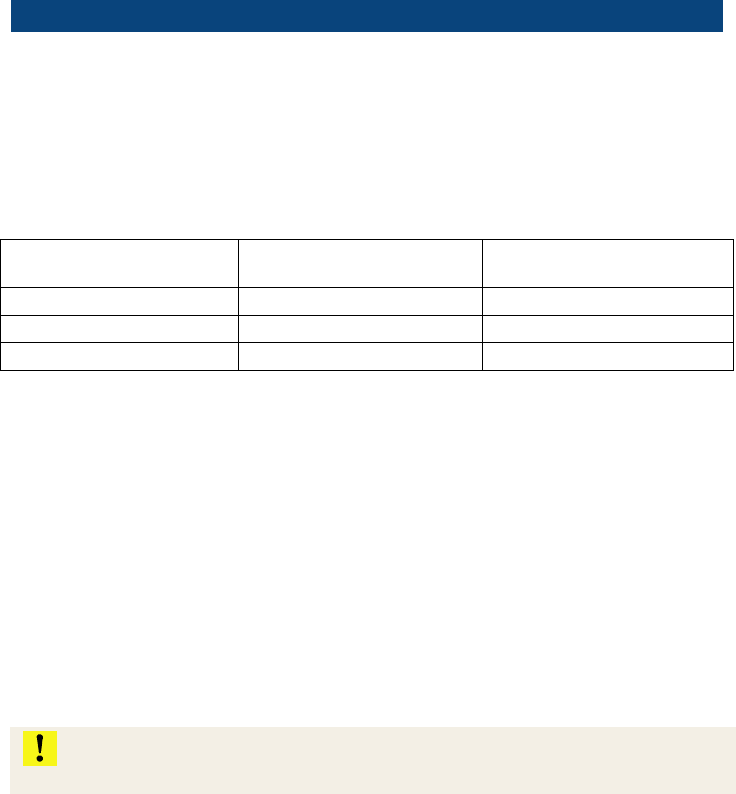
suitable for testing domestic exhaust systems. Table 3 shows the maximum internal
surface area for P, M and H tests with the corresponding sealing set type P, M + H.
Table 3: maximum internal surface area
Class
Leakage rate 0 l/min
Maximum permissible
leakage rate
P1
> 50m²
ca. 30m²
M1
ca. 25m²
ca. 3m²
H1
ca. 25m²
ca. 3m²
In the case of larger installations, a sectional inspection should be carried out. The indi-
vidual sections should not exceed the maximum internal surface area according to the
table above. A telescopic sealing bladder can be used for sealing sections (see accesso-
ries). For measurements with very high test pressure type H, it is particularly important to
ensure that the sealing bubbles are secured against slipping.
If it is not possible to check larger exhaust systems in sections, a measurement can be
carried out using the adapter 3.0 and the associated N hose set. The measuring accura-
cy must be observed when using the adapter 3.0 (see section 2). To carry out the leak
test, a suitable connection for the air hose type N and the pressure hose type P must be
provided by the customer. When positioning the connections, the distance between the
two hoses should be as large as possible. The measurement itself must be carried out in
manual mode with the required test pressure.
ATTENTION!
The adapter 3.0 must be selected in manual mode with the "Adapt.”-key!
In manual mode, the power of the fans can be adjusted with the arrow keys. The differen-
tial pressure must be monitored and adjusted by the user until the desired test pressure
is reached. Then the leakage rate of the system can be read on the display of the Wöhler
DP 600.
Differential pressure
45
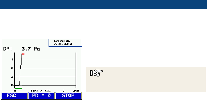
6 Differential pres-
sure
With the Wöhler DP 600 the user can perform a
differential pressure test. To do so select DIF-
FERENTIAL PRESSURE in the menu.
A diagram as shown on the left will appear that
shows the differential pressure of the last 4
minutes. The diagram can be stopped and print-
ed.
NOTE!
It is not possible to save the results of the differen-
tial pressure test.
Fig. 51: Differential Pressure Diagram

4 PA-Test
46
7 4 PA-Test
The Wöhler DP 600 Leakage Tester can perform the 4 Pa-test to control the underpres-
sure limit 4 Pa. The 4 Pa test controls if there is a sufficient combustion air supply ac-
cording to the DVGW (German Association of Gas and Water Engineers), Note G 625.
The test measures the differential pressure between the room where the fireplace is
installed and the ambient air, when the theoretically required combustion air is withdrawn.
The Wöhler DP 600 sucks the theoretically required combustion air and this way simu-
lates the fireplace. At the same time the instrument measures the differential pressure.
No additional measuring instrument will be necessary for the 4 Pa test.
WARNING!
Switch off the fireplace.
7.1 Preparations for the 4 Pa test
•
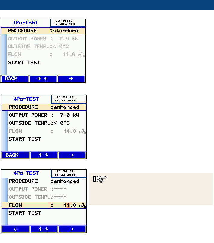
Select 4 Pa TEST in the main menu.
•
Select STANDARD PROCEDURE or ENHANCED PRODEDURE.
Fig. 52:standard procedure
For the standard procedure the fireplace has to be
connected to the exhaust gas system.
4 PA-Test
47
The user can directly proceed to prepare the
measurement.
• If the user has selected the enhanced proce-
dure, he must enter the output power of the
installation and the outside temperature before
starting the measurement.
The device will then calculate the flow automati-
cally.
NOTE!
Alternatively the user has the possibility to enter
the flow. In this case it is not necessary to enter
the output power and the outside temperature.
Fig. 53: Display, standard procedure
Fig. 54: Display, enhanced procedure
Fig. 55: Entering the flow
4 PA-Test
48
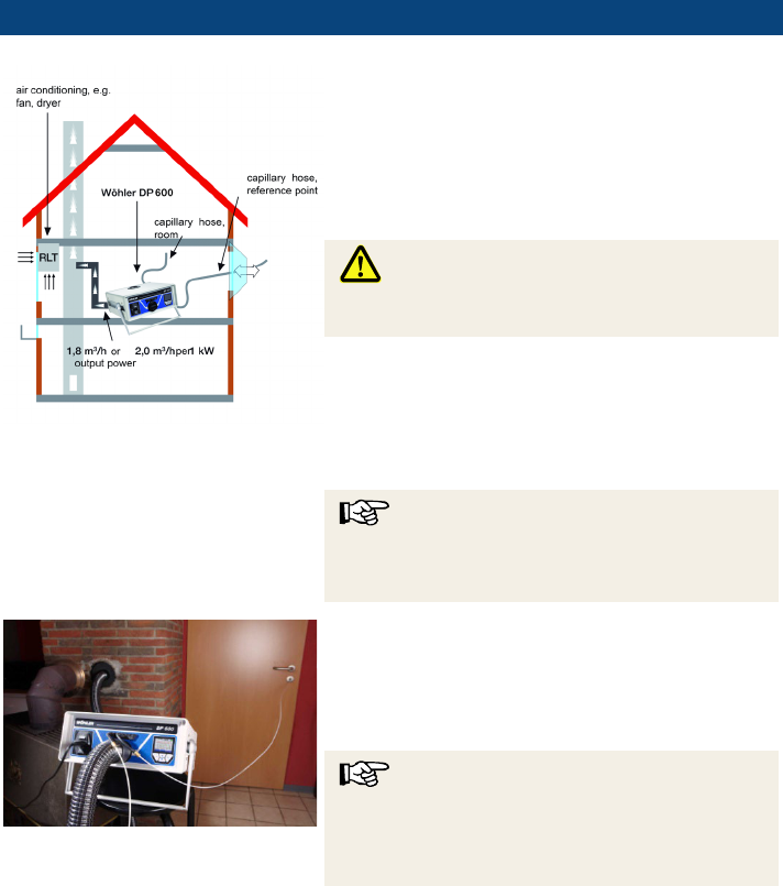
Fig. 56: Enhanced procedure
• For the enhanced procedure, the Wöhler DP
600 has to be connected to the fireplace in
place of the exhaust gas system.
•
Remove the connecting piece of the fireplace
and connect the plastic hose class N with a
suitable Sealing Element to the exhaust gas
system.
WARNING!
Make sure that there is no adaptor installed in the
Wöhler DP 600.
•
Plug the free end of the plastic hose to the air
connection (over pressure) (Fig. 1, part 11).
During the 4 Pa test the measuring instrument will
suck a constant amount of air from the fireplace
room.
NOTE!
When applying the enhanced or the standard pro-
cedure, it is necessary to open and to close the
window as described later in this chapter.
Fig.
57: Wöhler DP 600 with capillary
hoses during the 4 PA test.
When applying the standard procedure or the en-
hanced pro
cedure proceed as follows.
•
Connect the capillary hose, that leads to the
reference point (stairway or outside air), to the
negative pressure socket (fig. 1, part 5).
NOTE!
First remove the connection plug of the end of the
black capillary hose, so that you can plug the
hose to the hose nipple of the negative pressure
socket (fig. 1. part 5).
•
Connect the second capillary hose to the
positive pressure socket (fig. 1, part 4). The
second hose stays in the room where the fire-
place is installed. With this hose the march of
pressure will be recorded.
Underpressure in the fireplace room in relation to
the pressure at the reference point will lead to a
negative differential pressure.
4 PA-Test
49
7.2 Performing the 4 Pa test
How to perform the 4 Pa Pressure Test:
•
Switch on appliance and all air conditioning
(fan, dryer) with maximum power.
•
Open an outside window or a door to the
reference room and test proper operation of
the appliance, ensure that there are no back-
draft conditions.
•
How to position the reference capillary hose:
Lead the hose outside through a window seal
or into the stairways through the door rebate
or the keyhole.
NOTE!
Especially on stormy days, the stairways may be
a stable reference room.
If the stairways are used as reference room, all
windows, doors, cellar doors and trap doors have
to be closed.
Fig.
58: Pressure profile during the 4 Pa
Test
The second capillary hose will stay uncut in the
fireplace room.
•
Reset the pressure sensor by pressing „P
D
=
0“ (standard procedure) or enter the data of
the fireplace and the outside temperature (en-
hanced prodedure).
•
Press "Start" to start the 4-PA Test.
The meter will now record the pressure profile
for 4 minutes.
•
Open the window/door for about 30 seconds,
so that the zero line can be registered.
•
Close the window/door for about 30 seconds,
control underpressure.
•
Open the window/door for about 30 seconds,
the zero line should be reached again.
•
Close the window/door for about 30 seconds,
control underpressure.
•
Open the window/door for about 30 seconds,
the zero line should be reached again.
• Close the window/door for about 30 seconds,
4 PA-Test
50
control underpressure.
For a better orientation, every 30 seconds there
are auxiliary lines in the diagram. After a maxi-
mum of 4 minutes, the measurement will stop
automatically.
NOTE!
Press "Stop" to stop the 4 PA Test earlier.
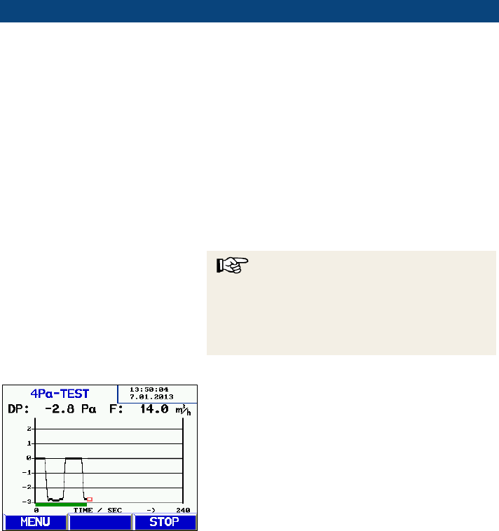
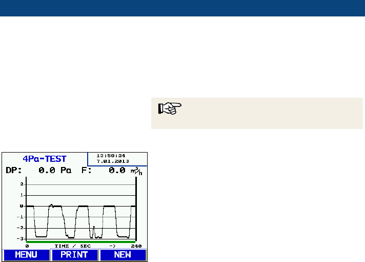
Fig.
59: Diagram 4 Pa Test
Normally a diagram as shown in figure on the left
will appear. The pressure peaks in the diagram
are caused by the rapid movement of the window
or the door and therefore they are not relevant for
the interpretation of the diagram.
In the figure on the left the pressure drop is about
2,0 Pa.
The reliability of the system is considered suffi-
cient, when the pressure drop caused by opening
and closing the window is less or equal to 4 Pa (8
Pa in the case of wood burning without surround-
ing air).
After the 4 Pa test is completed, "4 Pa Test" will
be marked by "4PA" in the main menu. Select
"Print" from the main menu to print out the read-
ings and select "Save measurements" to save
them.
Stove Test
51
8 Stove Test
The Wöhler DP 600 can be used to control the tightness of a stove. According to the
approval guidelines for the control of room sealed appliances, the requirements regard
the leak tightness of fireplaces with its necessary access lines for the combustion air and
the connection.
To control the leak tightness of a fireplace, the same procedure to control the leak tight-
ness of an exhaust gas system class N is applied. If possible use the Sealing Set Type N
and connect it as described in chapter 5.3) for the leakage test. You can purchase Seal-
ing Elements of many different forms and sizes. Nevertheless it may be necessary to
adapt the Sealing Element to the test object. In this case we recommend to use Sealing
Elements that can be cut individually. (see accessories).
Always install the adapter 3,0 for the stove test.
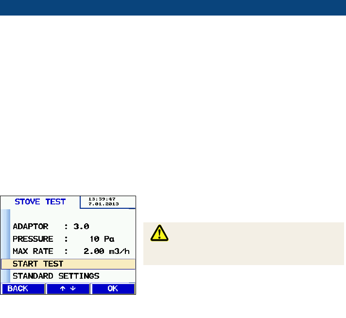
8.1 Performing the Stove
Test
• In the main menu, select STOVE TEST.
In the following display, enter the measurement
configuration. The figure on the left shows the pre-
setting.
WARNING!
Make sure that the adapter 3,0 is installed in the
Wöhler DP 600.
Connect the large air tube and the small pressure
tube to
the test object and start the measurement.
The measurement is the same as for the leakage
test. The Wöhler DP 600 will automatically deter-
mine the leakage rate of the test object.
Fig. 60: Presetting for the Stove Test
SETUP
52
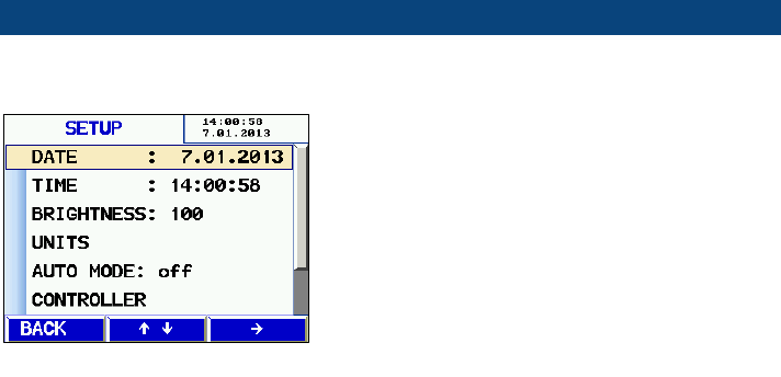
9 SETUP
• Go to the main menu.
Select the option "SETUP" to enter the main setup
menu. Proceed as follows:
•
Use the arrow keys to select and change the
parameters.
The parameter that can be changed appears in
red.
•
Press BACK to leave the parameter without
saving or press the down-key to save the new
setting and go to the next parameter.
Date
Change the current date of the internal calendar
(format 1.01.2013)
Time
Change the current time of the internal clock (for-
mat 12:00:00 AM)
Brightness
Adjust the brightness of the display between 0 %
and 100 %.
Units
Select the unit.
Pressure
Pa, hPa, mbar, mm/H
2
O, in/Wc
Flow rate (to enter for all adapters):
m
3
/h, CFM, l/h, l/min, l/s
Auto Mode
If the auto mode is activated, the Wöhler DP 600
will perform a complete measurement after it has
been switched on. In this case the user does not
have to enter anything.
The following statuses are possible:
off normal mode
std The Wöhler DP 600 will automatically
perform a measurement in the standard
mode with the last configuration.
Var The Wöhler DP 600 will automatically
perform a measurement in the variable
mode with the last configuration.
Fig. 61: Setup menu, upper display

SETUP
53
Controller
The Wöhler DP 600 works with a PI controller.
Normally there is no need for the user to adapt the
parameters of the controller. If the exhaust gas
system to be tested is especially large or small,
the user will have the possibility to adapt the con-
troller.
He can determine the reset time TN between 0,1
and 300 s.
He can determine the boost KP between 0 and
20.000.
Default
Reset the Wöhler DP 600 to its factory default
setting (except the calibration).
Printer logo
Enter a custom corporate logo (6 lines) that will
appear in every printout.
Data management
54
10 Data management
- The user can create a folder for every client and assign up to 100 legs to a client.
10.1 Save customer records
When different measurements have been per-
formed at one installation, they can be assigned to
a client as follows:
•
Select the SAVE option from the main menu.
•
Use the up- and down keys to navigate
through the menu. If there exists no folder of
the costumer, whose data shall be saved, yet
in the Wöhler DP 600 it can be created in the
"new customer" menu (see chapter
0).
NOTE!
Keep the up or down key depressed to scroll fast-
er.
•
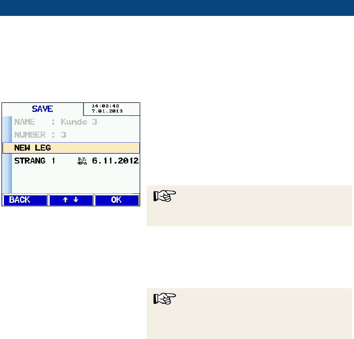
Confirm with OK .
The list of legs will appear. Select "NEW LEG " to
assign a new leg to this client.
•
Confirm with OK .
NOTE!
During the saving process, the data that has al-
ready been saved before under this leg, will be
deleted.
Fig. 62: Riser selection
Data management
55
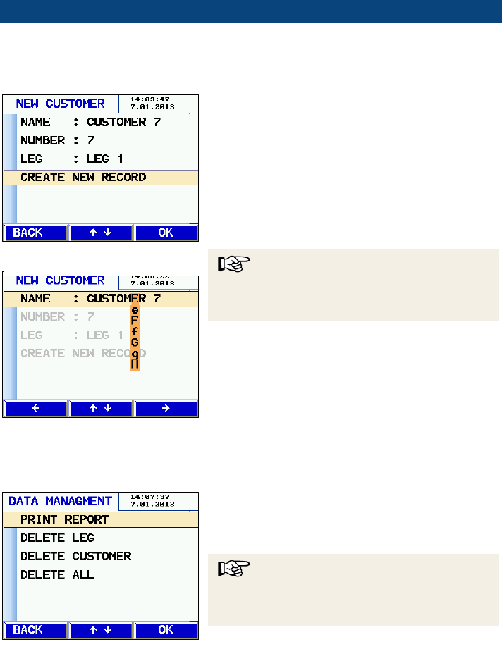
10.2 Creating a new cus-
tomer folder
The user can create new customer folders or new
legs
when saving the data.
•
Go to the main menu and select SAVE.
All customers will appear and the
option NEW
CUSTOMER.
•
Select NEW CUSTOMER.
•
Select CREATE NEW RECORD.
With the arrow keys, enter the name, a customer
number and the name of the
leg.
NOTE!
The user can save all together 100 legs and as-
sign them to different customers. The number of
legs assigned to a customer is arbitrary.
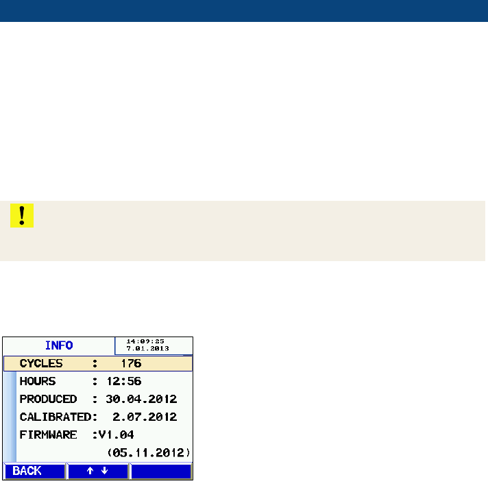
10.3 Option "Data management"
Select "PRINT REPORT" to print a report of any
saved measurement.
Select "DELETE LEG" to delete a single leg.
NOTE!
When there is only one leg saved in a customer
folder, the customer folder will be deleted when
the riser is deleted.
Select "DELETE CUSTOMER" to delete a com-
plete customer folder with all risers.
Select "DELETE ALL" to delete all customer fold-
ers.
Fig. 65: Option "Data management"
Fig. 63: Creating a new customer
folder
Fig. 64: New Customer
Data transfer with the PC or notebook
56
11 Data transfer with
the PC or notebook
The data can be transfered from the Wöhler DP
600 to a PC or notebook with the USB cable. To
do so the Software Wöhler DC 4xx/DP 600 is
needed.
•
Connect the USB cable to the USB port of the
Wöhler DP 600 (fig. 1, part 7) and the other
end of the cable to the USB port of the PC.
•
12 Calibration
ATTENTION!
Only authorized Wöhler Service employees may calibrate the device. Improper chang-
es may lead to incorrect results.
This menu can only be entered with a pass word.
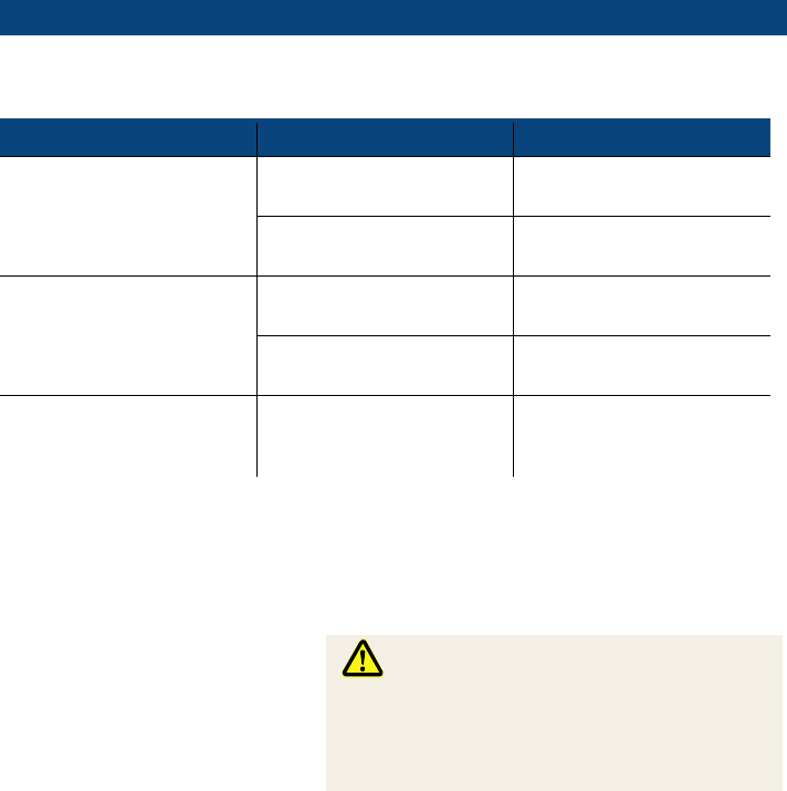
13 Info
Go to the main menu and select INFO.
In the display the number of measurement cycles,
the hours of operation, the date of manufacture,
the calibration date and the firmware version are
shown.
•
Fig. 66: Information
Fault indication
57
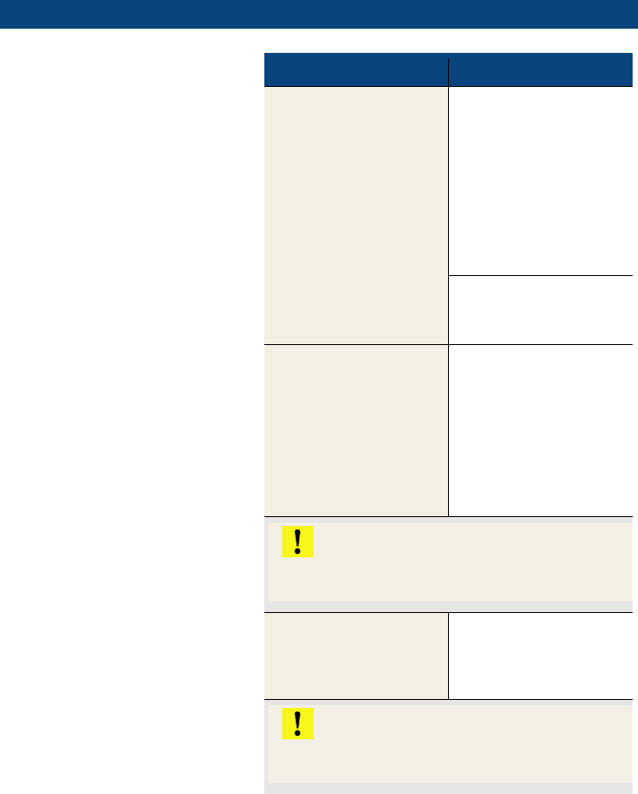
14 Fault indication
Error message
Possible reason
Solution
self test error (pressure)
Pressure on the line/storm
Switch off the device and
start again
Pressure sensor damaged
Send the instrument to a
Wöhler service point
self test error (flow)
Pressure on the line/storm
Switch off the device and
start again
Flow sensor damaged
Send the instrument to a
Wöhler service point
Overheat
Overheat
Remove adapter and let the
instrument cool down to
room temperature.
15 Maintenance
The Wöhler DP 600 does not contain any parts
that can be serviced. Therefore the instrument
should never be opened by the user.
WARNING!
The instrument may only be opened by a Wöhler
Service Employee.
Caution - Risk of death due to electric current!
230V 50 Hz
Maintenance
58
15.1 Maintenance work
Interval
Maintenance work
Depends on the usage,
but at least once a year
Slightly grease all
o-rings of the pressure
and air connection and
of the adapters.
In case of pollution
Change the filter pads
in the air connection -
under pressure
If necessary
change the primary fuse
- Disconnect the power
cord from the wall
socket.
- Remove the fuse
holder by pulling the
upper edge.
ATTENTION!
Only replace the fuse by another of the same
type.
Once a year
Control and Calibration
of the instrument by
Wöhler or an authorized
service point.
ATTENTION!
Only Wöhler service employees can calibrate
the Wöhler DP 600 in the factory.

Warranty and Service
59
16 Warranty and Service
16.1 Warranty
Each Wöhler DP 600 Leakage Tester will be test-
ed in all functions and will leave our factory only
after extensive quality control testing. The final
control will be recorded in detail in a test report
and delivered with any unit.
If used properly, the warranty period for the Wöh-
ler DP 600 will be twelve month from the date of
sale. Ware parts, e.g. filters are not covered by
this warranty.
This warranty does not cover the freight and pack-
ing costs when the device is sent to the factory for
repair.
Service by non authorized personnel or making
modifications to the analyzer voids any warranty.
16.2 Service
Wöhler has built our reputation on excellence in
customer service. Therefore, of course, we are
readily available to assist you after the warranty
period ends.
•
Send us the device and we will repair it and
return it to you with our package service.
•
Immediate help is provided by our technical
staff over the telephone.

Accessories
60
17 Accessories
Sealing Sets
Wöhler DP 600 Sealing Set Type P, M + H
for 200 and 5.000 Pa measurements
Order no. 2601
Sealing Element with hole 110 - 150 m
Order no. 3843
Extension tube 3,75 m for Ø 50 mm
Order no. 50676
Wöhler DP 600 Sealing Set Type N
for 20 and 40 Pa measurements
Order no. 2602
Sealing Bladder with gas lead through
Ø 40 – 150 mm (Sealing Bladder Compact)
Order no. 6566
Ø 150 – 350 mm
Order no. 7974
Ø 350 – 600 mm
Order no. 7966
Sealing Bladder without gas lead through
Ø 40 – 150 mm (Sealing Bladder Compact)
Order no. 6560
Ø 150 – 350 mm
Order no. 7971
Ø 350 – 600 mm
Order no. 7981
Sealing Elements
Sealing Element Set Square
Order no. 8220
Sealing Element Set Round
Order no. 8050
Sealing Element to be cut individually
Order no. 50783
4-Pa Test
Wöhler DP 600 Flexible Capillary, 6 m
Best. Order no.
2604
Software
Software CD Wöhler DC 4xx / DP 600
Order no. 997

Declaration of Conformity
61
18 Declaration of Conformity
The manufacturer:
Wöhler Technik GmbH
Wöhler-Platz 1, D-33181 Bad Wünnenberg
declares that the product
product name: Leakage Tester
model number: Wöhler DP 600
complies with the key safety requirements set down in the guidelines of the Council for
the Harmonization of the Legal Requirements of the Member States in relation to the
electromagnetic compatibility 2014/30/EU and the low voltage 2014/35/EU.
The following standards were availed of to evaluate the product in respect of the elec-
tromagnetic compatibility:
EN 61000 (electromagnetic compatibility EMC)
EN 55011, classe B, EN 55014, EN 55016, EN 55022 (radio interference)

UKCA Declaration of Conformity
62
19 UKCA Declaration of Conformity
The manufacturer:
Wöhler Technik GmbH
Wöhler-Platz 1, D-33181 Bad Wünnenberg
hereby declares that the following product:
Product: Leakage Tester
Model: Wöhler DP 600
is in conformity with the requirements of the following legislation:
Electromagnetic Compatibility Regulations 2016 and
Electrical Equipment (Safety) Regulations 2016
The following standards were used to access the products in terms of electromagnetic
compatibility:
BS EN 61000 (electromagnetic compatibility EMC)
BS EN 55011, classe B, BS EN 55014, BS EN 55016, BS EN 55022 (radio inter-
ference)
Bad Wünnenberg,
26.08.2024
Dr. Michael Poeplau, Geschäftsführer/Managing Director
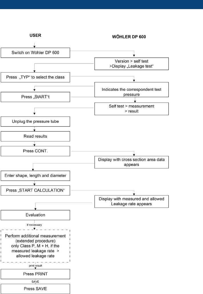
Brief instruction: Leakage Test, normal mode
63
20 Brief instruction: Leakage Test, normal mode
